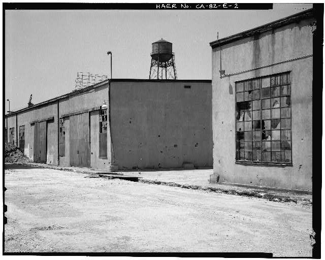
Ford Long Beach Assembly Plant Sheds C and D
The 1927 "Plot Plan" designed by Albert Kahn, Inc., does not illustrate Sheds C and D. Furthermore, the building permits do not indicate a construction date for the structure. The first illustration of these structures, labeled as Shed C, and Shed D, respectively, is on a 1947 map of the Long Beach Assembly Building (Plot Plan 74, 1947 LBP). The structures were situated east of the Pressed Steel Building, and north of Shed A. The 1948 drawing of the Bulkhead for the Ford Motor Company - Plot Plan (Davies, Plot Plan 1949, LBP) has a label "Storage Sheds" pointing to Sheds B, C, and D. The label "Shed" was attached to the outlines for Sheds B, C, and D on a map that the Ford Motor Company had prepared as part of a "Specifications" for sale of the property in 1959 (Long Beach Assembly Plant, Specifications in Offer to sell, 1959, LBP). A 1982 map of the former Ford property prepared by International Rectifier, Corp., Rachelle Laboratories, Inc. (1982, LBP) illustrates Sheds C and D as "Warehouse No. 3 and No. 4, respectively. Hence, the structures were used as storage sheds during and after the Ford occupation of the site.
Sheds C was the northern building, while Shed D Is the southern building, located northeast of Shed A. Shed C was a rectangular shaped structure, situated on a north/south axis. Dimensions for the structure were 290 feet along the north/south axis, by 40 feet along the east/west axis, with a total floor space of 11,600 square feet. Shed D was a rectangular shaped structure, situated on a north/south axis. Dimensions for the structure were 225 feet along the north/south axis, by 40 feet along the east/west axis, with a total floor space of 9000 square feet.
Sheds C and D were built upon a poured concrete pad. This pad was probably supported by pilings in the same fashion as described for the Assembly Building. Poured concrete piers rested on the concrete pad. These piers supported vertical, laminated beams or posts that formed the superstructure of the building. The posts were fabricated from three to five, 2 Inch by 12 Inch milled planks, that were fastened with carriage bolts. The posts were horizontally spaced at 30-foot center intervals. The posts were connected by a series of horizontal trusses that rested on wooden cleats, three ft. below the tops of the posts. These trusses were located along the north/south tending exterior walls and the solitary interior bearing partition. In effect, the post and truss construction resembles "balloon framing," a popular building technique In the mid-19th to early 20th centuries. The north and south ends of the building were balloon framed with milled 2 inch by 4 inch milled lumber. Horizontal and "A"-shaped braces were used to reinforce the skeleton of the structure along the east/west axis, between the exterior walls and the solitary interior partition.
Wall construction was facilitated with stick framing that ran from the bottom of the trusses down to the concrete pad where they were anchored. Drywall was applied to the exterior and interior or the buildings frame. The exterior walls were finished in stucco and painted a tan color. The drywall on the interior walls was plastered, and painted.
The roof was a shed-type roof with a 1 percent west to east tending slope. It was constructed by fastening 2 inch by 8 inch milled rafters along an east/west axis, across the tops of the exterior walls and central bearing partition. Purlins, measuring 2 Inch by 4 inch ran atop the rafters in a north/south axis. Wooden sheathing was affixed to the top of the purlins, and supported the asphalt roofing material.
Fenestration consisted of steel and glass sash. The windows were 3 feet wide by 8 feet long (high) and 6 feet wide by 8 feet long (high), allowing ample light to filter into the interior of the structure. Corrugated steel doors, measuring 5 feet wide by 10 feet high, were mounted on sliding tracks on the eastern and western sides of the storage sheds. The placement of these doors permitted easy access to the buildings from railroad cars that carried materials along the railroad tracks formerly situated on the east and west sides of these buildings (Plot Plan LB 74, Long Beach Plant, 1947, LBP).
Mechanical systems were intact in Sheds C and D. The overhead fire sprinkler was in-situ among the trusses and bracing, elevated above the floor. Electrical circuit boxes and conduits were evident on the interior walls. Light fixtures were affixed to the underside of the rafters. A fire-hose holder and controls for the fire system were observed in both sheds.
These sheds embody the same characterists represented In the main assembly building. The buildings were constructed with a massive frame that permitted the optimal use of floor space, yet allowed ample natural light and access into the buildings.

VIEW TO NORTH SHOWING RAIL SPUR, SHEDS, AND NORTHWEST CORNER OF SHED A, AT RIGHT.

EAST SIDE DETAIL OF SHEDS C AND D. VIEW TO SOUTHWEST.

SHED D INTERIOR, LOOKING SOUTH.